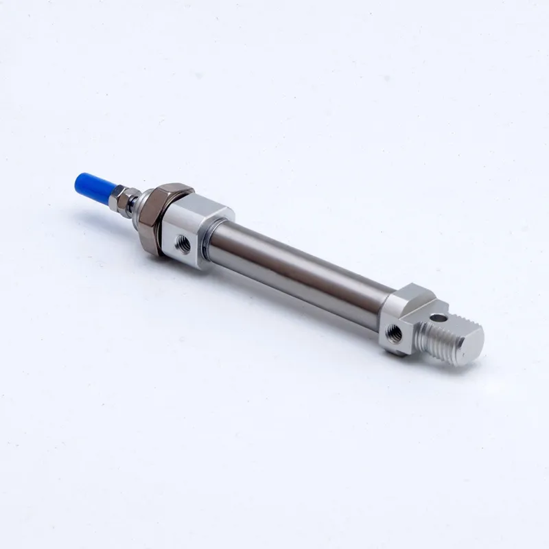
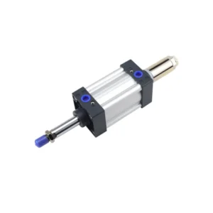
Hered MI Series Mini Stainless Steel Cylinder
Hered Pneumatic Co., LTD.’s MI Series Mini Stainless Steel Cylinder is a compact, high-performance actuator designed for various industrial applications. Featuring corrosion-resistant construction, anti-collision pads, and versatile mounting options, this cylinder offers exceptional durability and flexibility in challenging environments.
Key Features
- High-strength stainless steel tube body with surface strengthening treatment
- Fixed anti-collision pads to reduce reversing impact
- Multiple rear cover options for flexible installation
- Riveted roller pack structure for reliable connection
- Polyurethane axial dust seal for long service life
- Low friction piston seal design for smooth operation
- Compliant with ISO6432 standard
Specifications
- Bore Sizes: 8, 10, 12, 16, 20, 25mm
- Motion Patterns: Double-acting (Cushion Buffer/Air Buffer), Single-acting
- Working Medium: Air (Filtered by 40 μm filter mesh)
- Operating Pressure: 0.1-1.0 MPa (double-acting), 0.2-1.0 MPa (single-acting)
- Proof Pressure: 1.5 MPa
- Working Temperature: -20 to 70°C
- Working Speed: 30~800mm/s (double-acting), 50~800mm/s (single-acting)
Symbol for MI Mini Cylinder
Specification for MI Mini Cylinder
| Bore (mm) | 8 | 10 | 12 | 16 | 20 | 25 | |
| Motion Pattern | Double-acting Cushion Buffer, Single-acting | Double-acting Cushion Buffer, Double-acting Air Buffer,Single-acting | |||||
| Working Medium | Air (Filtered by 40 μm filter mesh) | ||||||
| Working pressure range | Double-acting | 0.1~1.0MPa (14~145Psi) | |||||
| Single-acting | 0.2~1.0MPa (28~145Psi) | ||||||
| Proof Pressure | 1.5MPa (215Psi) | ||||||
| Operating temperature range | -20~70℃ | ||||||
| Operating speed range | Double-acting: 30~800 mm/s; Single-acting: 50~800 mm/s | ||||||
| Stroke Tolerance Range | 0~100: +1.0/0; >100: +1.4/0 | ||||||
| Buffer Type | MIC: Adjustable Air Buffer Others:Cushion Buffer | ||||||
| Port Size | M5×0.8 | G1/8 | |||||
Standard Stroke
| Bore (mm) | Standard Stroke | Max. Stroke | Allowable Stroke | |
| Double-acting | 8,10 | 10 15 20 25 30 40 50 75 100 125 150 | 150 | 200 |
| 12 | 10 15 20 25 30 40 50 75 100 125 150 175 200 | 200 | 300 | |
| Double-acting Double-acting Air Buffer |
16 | 10 15 20 25 30 40 50 75 100 125 150 175 200 | 200 | 300 |
| 20,25 | 10 15 20 25 30 40 50 75 100 125 150 175 200 250 300 350 400 450 500 | 500 | 650 | |
| Single-acting | 8,10,12 | 10 15 20 25 30 40 50 | 50 | – |
| 16,20,25 | 10 15 20 25 30 40 50 75 100 | 100 | –
|
|
Ordering Code

Internal Structure

| No. | Item | Material | No. | Item | Material | No. | Item | Material |
| 1 | Hex nut | Carbon Steel | 2 | Piston rod | Durionise Grinding Rod | 3 | Dust-proof ring | TPU |
| 4 | Hex nut | Carbon Steel | 5 | Front cover | Aluminium Alloy | 6 | Crash Cushion | Elastic material |
| 7 | Cylinder Barrel | Stainless steel | 8 | Piston Seal | NBR | 9 | Magnet ring | Magnetic material |
| 10 | Wearing ring | Wear Material | 11 | Piston | Aluminium Alloy | 12 | Hex socket cap screw | Carbon Steel |
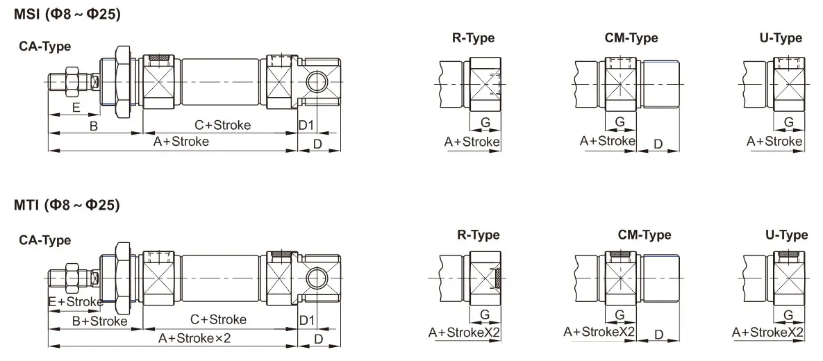
Overall and Dimensions
MI (Φ8~Φ25), MIC (Φ16、Φ20、Φ25)
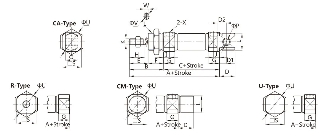
| Bore/Symbol | A | B | C | D | D1 | D2 | E | F | G | H | I | J | K | L | P | Q | S | U | V | W | X |
| 8 | 74 | 28 | 46 | 12 | 2 | 6 | 16 | 12 | 10 | 12 | 6 | 6 | M4×0.7 | M12×1.25 | 4 | 8 | 15 | 17 | 4 | – | M5×0.8 |
| 10 | 74 | 28 | 46 | 12 | 2 | 6 | 16 | 12 | 10 | 12 | 6 | 6 | M4×0.7 | M12×1.25 | 4 | 8 | 15 | 17 | 4 | – | M5×0.8 |
| 12 | 88 | 38 | 50 | 17 | 3 | 9 | 21 | 17 | 10 | 16 | 6 | 6 | M6×1.0 | M16×1.5 | 6 | 12 | 18 | 20 | 6 | 5 | M5×0.8 |
| 16 | 94 | 38 | 56 | 17 | 4 | 9 | 21 | 17 | 10 | 16 | 6 | 6 | M6×1.0 | M16×1.5 | 6 | 12 | 20 | 22 | 6 | 5 | M5×0.8 |
| 20 | 106 | 44 | 62 | 20 | 9 | 12 | 24 | 20 | 14 | 20 | 7.5 | 7.5 | M8×1.25 | M22×1.5 | 8 | 16 | 25 | 29 | 8 | 6 | G1/8 |
| 25 | 115 | 50 | 65 | 22 | 11 | 12 | 28 | 20 | 15 | 22 | 8 | 8 | M10×1.25 | M22×1.5 | 8 | 16 | 30 | 33.5 | 10 | 8 | G1/8 |
| Bore/Symbol | A1 | A2 | B | C | T |
| 8 | 102 | 103 | 28 | 46 | 15 |
| 10 | 102 | 103 | 28 | 46 | 15 |
| 12 | 126 | 126 | 38 | 50 | 21 |
| 16 | 132 | 132 | 38 | 56 | 21 |
| 20 | 150 | 150 | 44 | 62 | 24 |
| 25 | 165 | 164 | 50 | 65 | 27 |
| Bore/Symbol | A | B | C | D | D1 | E | ||
| Stroke | 0~50 | 51~100 | 0~50 | 51~100 | ||||
| 8 | 101 | – | 28 | 71 | – | 12 | 2 | 16 |
| 10 | 101 | – | 28 | 71 | – | 12 | 2 | 16 |
| 12 | 116 | – | 38 | 75 | – | 17 | 3 | 21 |
| 16 | 123 | 148 | 38 | 81 | 106 | 17 | 4 | 21 |
| 20 | 140 | 165 | 44 | 87 | 112 | 20 | 9 | 24 |
| 25 | 151 | 176 | 50 | 90 | 115 | 22 | 11 | 28 |
Construction
The MI series cylinders feature high-quality components, including:
- Stainless steel cylinder barrel
- Aluminum alloy front and rear covers
- Durionise grinding rod for piston rod
- NBR piston seals
- TPU dust-proof ring
- Wear-resistant materials for wearing rings
Applications
- Food and beverage processing
- Pharmaceutical manufacturing
- Chemical processing
- Packaging machinery
- General industrial automation in corrosive environments
Installation and Use Guidelines
- Select cylinders with sufficient output power for varying loads
- Use appropriate cylinders for high temperature or corrosive conditions
- Implement protective measures in high humidity or dusty environments
- Clean pipelines before connection to prevent debris entry
- Use filtered air (40μm or finer)
- Take anti-freezing measures in low-temperature environments
- Perform no-load testing before operation
- Avoid lateral loads to maintain normal operation and prolong service life
For detailed specifications, model options, or customized solutions, please refer to the provided dimension tables and ordering codes. Our technical support team is available to assist you in selecting the optimal MI Series Mini Stainless Steel Cylinder for your specific application requirements.


